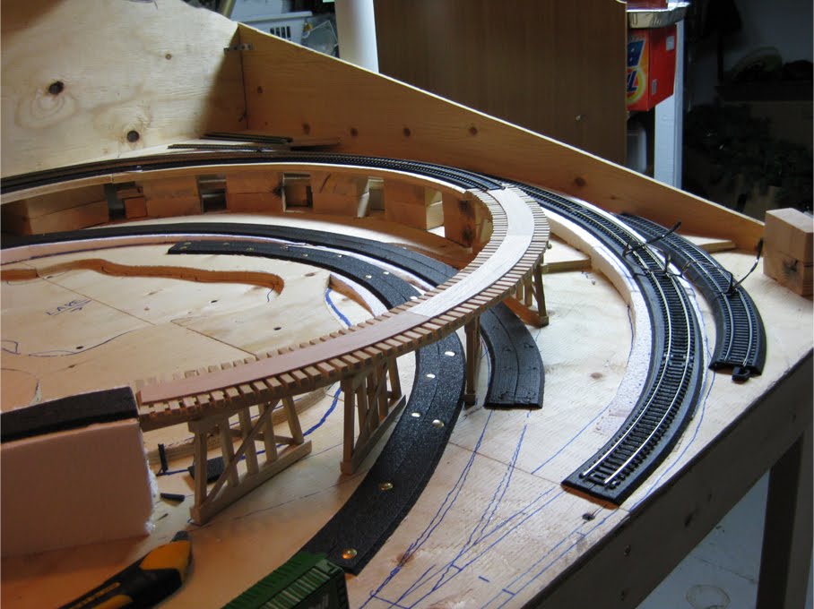
After a week, I finally completed my trestle. I built it using 1/4” and
3/8” square doweling rod purchased from a local hardware store. I first
traced on a large sheet of paper the track curve, as well as the location of
the tracks that would pass below. From this, I determined the measurements
as well as the location of each pier.
I built the deck of the trestle directly onto the drawing that I had made,
using this as an exact guide for placing the pieces. This was the best
option to keep everything accurate. The piers had to be on a sharp angle due
to the two tracks passing below so extra support had to be given to the
trestle deck in some areas. I finished the piers with 1/16" cross supports
as well as a deck for the 18" radius track to sit on. Even thought this is
not the most prototypical trestle, it still looks good on the layout and
fits the track perfectly.
By this time I have placed all of my track bed with the exception of the
front staging area. I just want to be sure of my turn out positions before I
glue anything down permanently. You can finally get a good idea of how my
layout is going to look.
On my last day off, I added the trackbed for the upper mountain tunnel
lines. The outer track is part of the main oval line, which will descend
down to the front staging area. The second ascends up from the track
crossing in the center of my layout to the raised area at the rear of the
layout. This line and the main line run together in one tunnel portal. I
have also laid the track through the lower tunnel portal . I completed this
so I wouldn't have to work around the upper sections of track in the
future.
This wraps up my Canada Day long weekend. My plan for the following week
will be to get a good start on the large wooden trestle.
On Saturday I decided to tackle the bridge that will carry both the oval
main line and figure-eight line of track in the rear section of the layout.
For this, I purchased a set of pier girders as well as a warren truss bridge
kit. With a little modification, I attached two bridge girders together
using a third girder.
When these were dry, I attached bridge sides of the warren truss kit to the
girder deck. I used a few scrap pieces of styrene to add additional support
to the trusses. The final look and design looks pretty decent. I placed the
bridge onto my layout and used foam shims on each end so it was level with
the track. I then finished with butting foam roadbed right up to the bridge
deck.
The bridge will still need to be painted to for some added realism, but
this will happen at a later time. I also had to add a foam extension to the
main line curve as shown in the photo below (under the 15 pound weight).
This extension was the result of a measuring mistake I made early in my
original planning. Thankfully this was an easy fix. Trackbed was also added
at this time to both tracks at the rear of the layout.
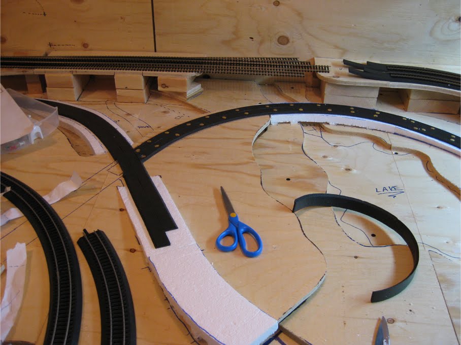
The next section that I wanted to complete was the stretch of track that
would travel down from the trestle, below the main line, and loop back into
the front switching are. This section will be part of a tunnel in the future
so I decided to complete it now before I did too much work on the tracks
above it. The foam roadbed was the first step after planning the track path.
Once again, I used thumb tacks to hold the roadbed in place while the glue
dried.
At this time I also installed the segment of roadbed for the section that
will travel from the front staging area, around the lake area and up onto
the mid-section of the layout. This will cross the part of track that
descends from the trestle at a 60 degree angle.
With July 1st this year being on a Thursday, my work decided to shut down
for IT upgrades on Friday as well, giving me a nice long 4 day long weekend
- plenty of time to make some serious progress on my model.
I first fixed my original ramps on the left side of my layout. I shaved
them down with a sharp knife and placed different sized risers underneath to
make them much more gradual and smooth. I also laid foam trackbed on the
right side of the layout leading up to the future trestle.
The second approach to the trestle is also constructed at this time. This
unfortunately is going to be the most challenging part of the layout as far
as track goes as the total grade here is about 11%. This however, is a risk that just needs to be taken for the sake of
the rest of the layout. I’m sure it will all work out in the end. For track
planning, I commonly used Bachman E-Z Snap-Track to plan where my actual
track and foam roadbed would go. This track works great as a moveable
template and grade planner when working with 18” radius curves.
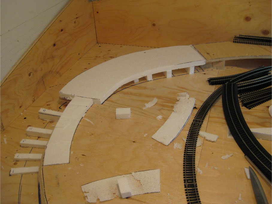
Over the last month or so I have been building the ramps to allow the
tracks to go from one level of my benchwork to the next. I purchased 3/4”
sheets of Styrofoam and used this for each of the ramps. It took several
attempts to get them right as it's quite difficult to get a perfectly even
and level transition from one level to the next level. There are other
products available to make this process much easier, such as Woodland
Scenics foam risers, but I’m determined to use what I have!
The first ramp completed successfully is the right curve of the main line
oval. After hours of trying to get everything just right, it was time to lay
down the very first section of foam trackbed. I glued down one half at a
time in about 20” lengths. I used WeldBond multi-purpose glue and thumb
tacks to temporarily hold the track bed in place while it dried. Once the track bed was dry, I loosely placed 22” radius track to make sure
everything fit, which it did.
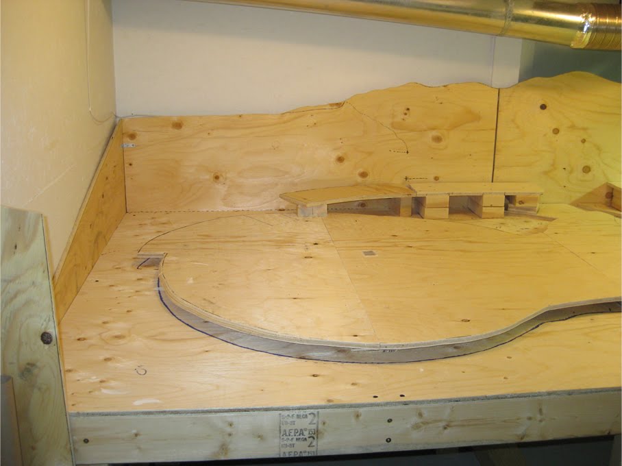
The main benchwork elevations are complete! To get the actual sections to
match my original planned elevation sections (which I marked out earlier on
the table), I first took large sheets of news print and laid them out to
cover the entire sections. The paper was thin enough that I could see the
lines I drew on the benchwork beneath it and thus traced the sections onto
the paper.
I then used the paper template to draw the elevated sections onto a new
sheet of plywood. Using a jigsaw, I cut the sections out. These all fit
perfectly on the table. I used scrap pieces of wood at varying heights to
support the new elevation sections depending on how high I needed them to
be.
The majority of the layout is raised up from the original table with only
the very front staging section at an elevation of 0. The back section is
raised 3 1/2” to allow for a double-mountain tunnel, as well as a bridge and
trestle. The left half of the layout is raised 1 1/2” and acts as an
elevated half way point for the descending track from the trestle and the
climbing track from the lake/swamp area. The top right area has a raised
section leading to the start of the future trestle.
Once my base table was completed, I re-applied the Atlas track templates
back onto the table so I had a good approximation of how my final track was
going to fit.
I then cut my side and back scenery walls to a size and shape that seemed
appropriate for what I was trying to accomplish. At this point I still am
not exactly sure what I am going to use for a backdrop, however I left
plenty of surface area if required later. I then simply screwed the pieces
onto the sides of my bench, using metal braces where the panels joined
together.
After the side and back panels were attached, I used the track templates to
plan the different elevations that were going to be required for the layout.
I visualized the different elevations I wanted and marked them out directly
onto the table. These sections will later be cut out on a separate piece of
plywood and attached with risers to their required heights.
After 2 weeks of planning, measuring, cutting, and measuring again, the
main bench is finally completed. The bench is actually two 4x4 tables which
bolt together with removable legs and frame. This allows it to be broken
down and removed from my basement (which is going to be a painful task if it
is to ever happen). I now have the base to start my layout.
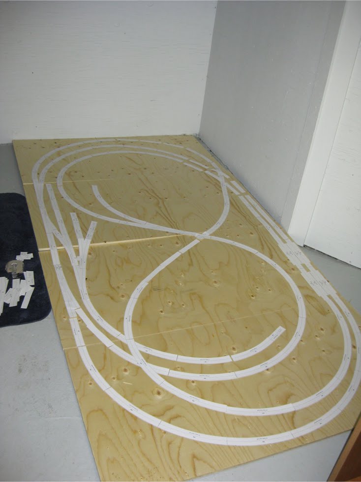
After clearing out a good portion of my tiny basement back in February, I moved down my
future table top which I cut into four section so I could fit it down the stairs. I copied and cut out Atlas track templates and laid them out on the
plywood. I could now see exactly how the track would
eventually lay out and knew that my computer-designed track layout would
translate well to the 4 x 8 benchwork size. The templates also allowed me to see some
areas where adjustments needed to be made.
Construction began back in February of this year, so I have about 6 months
to catch up on. Over the next several days I will post my progress from
February 15th right up to today (July 16th, 2010). After that, I will post
often so things are always recent. I have also updated my blog pages listed
above, so please check them out for a bit of background information on this
project.


